Commissioning, Part 5, Advancing Your Solar Utility Project

Time to begin to realize a return on your investment.  Once constructed the commissioning process consists of verification, testing, and sometimes rework. 

On your Marks, Get Set,

Time to begin to realize a return on your investment.  Once constructed the commissioning process consists of verification, testing, and sometimes rework.  Ideally the amount of rework is minimal because testing has taken place during construction.  The phrase that “quality is best when designed in” becomes evident when the time for interconnect to the grid finally comes.

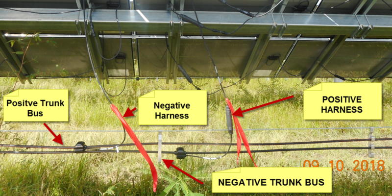
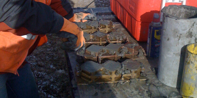
Commissioning verifications and tests vary depending on the system configuration and if any pre-commissioning testing is done.   Tests can include looking using thermal imaging to reveal high-resistance connections, amperage tests on tracker motors to test for binding.  Some ground faults are not detected by the inverters, requiring specific testing.   

Make the Plan, Follow the Plan

Meeting the testing requirements of the various permitting agencies and do so in an efficient manner is itself a dauting task.  Retesting, doing the same test to satisfy different agencies can be time consuming, costly, and impact the interconnection commitment.  Best practices are to perform as much testing in advance of the final commissioning activities.

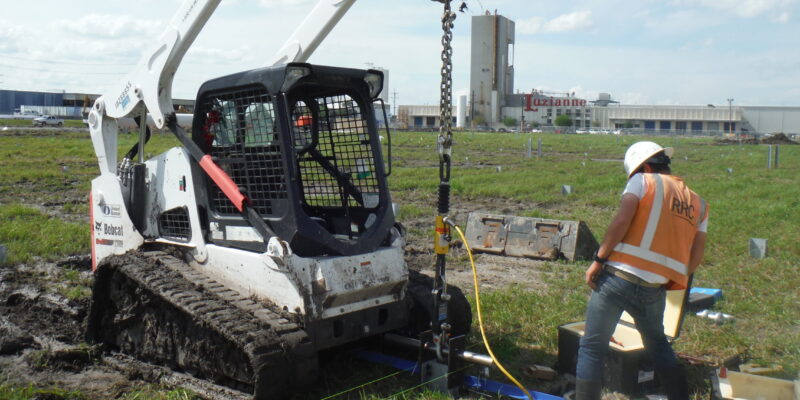
Visual inspections during construction that are completed as each string is completed.  Mechanical (tracker) testing can be done as each block is completed, and so on.  A full list of testing activities, and testing sequences is extensive and can consist of thousands of pages of checklists.  Utility solar construction companies have teams dedicated to the commissioning phase. 

For the journey leading up to commission, we invite you to our blogs on Preliminary Design through Construction at: https://rrccompanies.com/from-concept-to-reality-advancing-your-solar-utility-project/

Construction, Part 4, Advancing Your Solar Utility Project

Now that your Utility Solar Project has been permitted, designed, and fully financed, it’s time to build!

A Ground-Breaking Experience

It is too often the perspective of the engineer that once the drawings are handed over to the constructor, their job is done.  This is rarely the case.  Construction is where reality and the engineering design meet, and reality always wins.  For example, if the Land Survey did not represent the reality of the land, issues with flood control will win.  If the Civil grading plan is based on that same survey then the cost of moving, importing or exporting fill will win.  Issues arising during construction are greatly multiplied with solar utility projects because of the shear scale involved.

One approach is to dial into great-detail the profile of the land, the accuracy of the topo and geological studies.  However, there is a point of diminishing returns.  It’s better to also have a plan to be prepared to address and solve construction problems when they arise.  This is where boots on the ground combined with subject mater experts in the office has found to be the winning combination.

Keeping Your Eye on the Prize

It is a common approach in the oil, gas, pipeline and similar industries to have on-site personnel working with engineers “back at the home office” to address and solve problems when they arise.  Solar project construction also benefits from this approach.  Having one or two people on-site may seem like a cost to avoid, but in comparison to loosing tens of thousands of dollars for each day of construction delay, it is a low-cost investment.  Common stories include reworking the drainage plan due to issues with culverts, or saving on the cost of non-native fill by being smarter about the compaction plan. 

Having an owners-engineer on site helps to ensure construction follows the plan.  Having a construction-engineer on site with home-office backup helps ensure construction problems are resolved quickly.

Knit-One, Purl Two

Another best practice in the construction phase is to build a PV string to completion to serve as a model / template.  Not only does it provide a visual example for workers who may be new to solar construction, it also is the proving ground for things like wiring relief (slack) lengths, wire bend radius, bolt torquing, wiring termination examples, and the like.  The quicker the sample string can be put up and “certified” the quicker materials issues can be uncovered along with having an on-site classroom for the construction crew. 

Because there is so much to the build that is repetitive, having one string completed gives  workers an extra ability to figure out clever ways to be more efficient, either with methods or tools.

Building out the site and seeing it come together is the exciting, albeit mundane part of the project.  Like a marathon runner putting one foot in front of the other, the construction of a solar utility site requires steady forward progress repeating one step after another.

Part 3, Detailed Design, Advancing Your Solar Utility Project

Welcome to day 3 of this short 5-part series following the progression of a utility solar project from idea to interconnection.  Today we touch on Detailed Design. 

Details, Details

“It all works until you get down to the details”, that is what my dad used to say.  Hopefully once you have passed through the Feasibility and Preliminary design phases you won’t come to a point in the Detail Design phase that kills the project (see day #2 for some important helps with that).

Detail design is where drawings, written specifications, etc. specify the final configuration and layout of the equipment, the materials with their quantities,  and very importantly specifying information used during  construction.

It all Looks Good on Paper

I learned early in my engineering career that just because it looks good on paper, it doesn’t mean that that it can be built.  I also learned that sometimes it’s better to let the construction contractor  follow best practice rather than for me to dictate all the details.   

The detail design in a solar project carries the characteristic that a single “error” can have the multiplying effect.  It can impact of thousands of connections, or pieces of equipment.  One example is a simple thing like specifying the type of wire tie-wrap.  One type will last for years, one will degrade in a matter of months.  Since there can be 10,000+ tie wraps, if they embrittle in the sun and need to be replaced, that simple error can lead to large rework and warranty costs.   Specifying a structural bolt that carries with it the need for specific testing can lead to huge costs, not because the bolt won’t do the job, but because the bolt specification requires testing.  The wrong corrosion code for the steel piles is something we have seen.  Imagine finding that once you have 8,000 piles in the ground.  Easily overlooked is specifying cable cuts to minimize the leftover cable on the reel.  This is a “real” problem in cases where splicing is not allowed for underground cables.  If this isn’t considered when the cable is being purchased, the entire construction schedule can stretch out waiting for more cable from the vendor.  Delaying construction is very costly.  The list goes on and on.  

Who’s on First?

One of the difficulties in our industry can be that projects are “piecemealed” together.  One company will do the Feasibility, another Preliminary Design, and yet another Detailed Design.  Because different engineering companies have different ways of doing things, specifically how all the different drawings and specifications work together, having a properly integrated final design package can be a problem.    If one drawing refers to another drawing, or one specification refers to another, someone needs to verify the validity of the reference.

Experience Matters

Successfully completing the Solar Detailed design phase requires experience engineer working with people who have installation and construction experience.  Often companies will send their engineers to the field to get a good dose of reality.  Some companies lean heavily on standardization of design, some are very good at capturing lessons learned and maintaining a knowledge database.  All are good strategies and have their pros and cons.   There is little substitution for experience and not rushing through the Detailed Design Phase.  You can, but likely will pay a big price in the construction phase.

For Day #1 Feasibility, click here

For Day #2 Preliminary Design, click here

Advancing Your Solar Utility Project, Part 2, Preliminary Design

Welcome to day 2 of this short 5-part series following the progression of a utility solar project from idea to interconnection.  Today things get real with Preliminary design.  (For Day #1, click here)

Jumping Into The Deep End

Preliminary design is where excitement and dread start to come together.  It’s like that moment when you jump from the high point of a cliff towards the deep lake below.  Things get very real very fast.

Preliminary design in the renewables industry is often termed 30%.  Some clients however ask us to jump from 10% directly to 60% design as the preliminary phase.  Either way the intent is the same.

Roughing it Out

The preliminary design of a solar project is focused on solar collector layouts, locations for major pieces of equipment, roads, storm water control, and the like.  This work primarily involves Civil and Electrical engineers.  It pre-supposes that the Land Survey information and Geotechnical Report are accurate.  Often an initial PV panel layout is used as the starting point.  Sometime other land constraint information must be considered such as environmental zones, setbacks, etc.

Risks and Rewards

What we typically see are requests for preliminary design work that is only focused inside the fence line.  We also see incomplete survey or geotechnical information.  Sometimes this is acceptable, sometimes it presents a lurking risk.

Transmission Lines: Permitting and approvals outside the fence line is overlooked in a large majority of what we see.  A significant risk exists if the transmission line needs to pass through a parcel where access is denied.  Because the T-Line to the utility interconnect substation is typically long, overhead lines are best.  However overhead lines may be denied by local authorities then requiring costly buried lines.   Similarly examining the need for a local substation, or a project substation adjacent to the utility connection substation is often overlooked until later in the design process which can be a costly mistake.

Solar Racking Piles: The information gained from a geotechnical investigation and report is very important for many aspects of the site design, however there is a significant reward (cost savings) that can be realized by adding on-site pile driving and pull-testing.  This is something seldom done at the 30% stage but something that can save hundreds of thousands of dollars in the cost of the steel solar piles.

Boots on the Ground:  We highly recommend sending qualified, multi-disciplined individuals to the site at the 30% design stage whenever possible to visually verify the 10% information and look for things that have been missed.  This is roughly equivalent to sending out an engineering inspector to a commercial building that you might be considering purchasing.   

Some of the stories that come back from these trips never cease to amaze.  Stories like, “we found out that the owner who leased the property also signed a contract to allow cattle to graze” remind us that developing a solar project can be full of surprises. 

From Concept to Reality: Advancing Your Solar Utility Project

Welcome to part 1 of a 5-part series following the progression of a utility solar project from initial idea to pumping out power. 

Lifecycles and Waterfalls

Utility solar projects fall into the general category of the “waterfall” life-cycle.  One phase is started, progresses, then finishes before then the next phase begins.  The waterfall project method is what is traditionally used for construction projects, in contrast to Agile or iterative project life-cycles found in the software or marketing industries.  The development of project management methodology is a relatively recent reality and its’ standardization even more recent.  (ref: A Brief History of Project Management). 

In the utility solar industry, the project management waterfall phases are generally;

  • Feasibility (10% design)
  • Preliminary Design (30-60% design)
  • Detailed Design (90% – IFC)
  • Construction
  • Commissioning and Start-Up

Feasibility, Risk and Reward

Evaluating a solar project in the feasibility phase is similar to any large land development project in many ways.  Environmental, permitting, financing and construction issues are evaluated alongside projected ROI and these are influenced by revenue projections, short and long-term costs, local and even geo-political forces. 

From the perspective of an engineering company, such as RRC, assisting a developer in the project  feasibility phase is all about providing comprehensive technical and constructability information.

Even when the focus is on these two facets, performing the analysis requires a multidisciplinary approach, especially when it comes to identifying risks  One overlooked factor, such as the downstream impact of flooding, or wide variations in soil properties have the potential to derail or add significant cost.

Optimization in the Feasibility Phase

The value that is most often missed in the feasibility phase is the looking forward to the later life-cycle phases where the detailed engineering occurs.  This type of optimization is typically reserved for later project stages but with large utility solar projects it is important that it is a part of the feasibility phase. 

For example, optimizing for civil grading to reduce tracker costs may actually increase overall project costs.  Optimizing the PV layout may be a matter of being creative with different tracker configurations, pile designs, and the like.   Adding storm water control to minimize local scour around piles may be a better solution than excessive grading and soil stabilization.

All these are factors that may be too costly to refine in the early stages but may have a significant impact down the road.  Having an experienced multi-disciplined team able to look at the potential site and apply their wisdom is a prudent part of the feasibility phase for a solar project.

Solar Project Development, The Importance of Experience

The path to developing a solar farm can be long, winding, and risky.  Like most large-scale land development projects there are the permitting and financing issues.  Unique to solar is the multiplication of impacts a small miscalculation can impart.  By analogy, in the car industry, a miscalculation in the design of a component can lead to vehicle recalls costing many tens of millions of dollars.  In a solar project, a small technical miscalculation can change an investment from a winner to a loser.

Land development has been around for a long time and follows well established practices.  There are lots of people from commercial real estate and other industries who are entering the solar development arena because of current market opportunities.  Aiding these folks are software programs such as PVSYSTTM  and PlantPredictTM.   What is often lacking is the input of experience that avoids costly, or even financially disastrous miscalculations.

What The Software Can’t Tell You

“What is the buildable area?” is the most frequent question asked, and rightfully so as this has the strongest influence on power output, and therefore project financial viability.  The typical answer from the Geotechnical and Civil engineers is “that depends”, and this is where simply putting parameters into a software program falls short.  These two engineers can look together at the wetland, slope, drainage, and soil conditions and can suggest strategies and mitigations.  We have all seen how “one good idea” can change a loosing situation into a winning one, and that can apply here as well. 

“It all looks good on paper” is what the Construction Project Manager might say to those engineers.  Having a person with construction field experience giving input in the development phase is something typically overlooked by a person new to solar farm development.  Experienced solar developers and owners know that it is wise to consider factors that can impact construction schedules and cost.

The Optimization Balancing Act

Solar Project Optimization requires understanding what optimizes the Civil design, the Electrical design, (low, medium, and high voltages), structural design, and materials selection.  Optimization parameters can be in opposition to one another.  For example, optimizing the Civil grading plan may require more complex electrical layouts and more expensive tracker systems.  Sub-optimizing the Civil design in favor of the tracker selection can lead to complexities and cost in the structural (pile) design.  Add to these any special environmental or land use restrictions and you have the proverbial “Rubik’s cube” problem to solve.  Here also is where an experienced, multi-discipline team is essential. 

Inexpensive Insurance

It is not uncommon for a person to seek advice from a financial consultant, lawyer, or physician to get specialized, expert information or advice that they may not be able to find on the internet.  This is also true for solar project development.  There are companies, like RRC, that have the experience, the diversity of talent, and willingness to help developers to be successful, and typically for not a lot of cost.  As the complex circumstances of potential solar project sites increases, so to does the wisdom of including a team of experienced professionals to help you successfully navigate the journey.

For more on Developer services, visit our page: https://rrccompanies.com/services/developer-services/

A Day in the Life of an RRC CMT Expert

What Does a Wind Farm Construction Materials Testing (CMT) Technician Do?

By: Chris Alexander, Senior Engineering Technician

Senior Engineering Technician and CMT Project Manager, Chris Alexander, walks us through a day in the life of an RRC companies’ Construction Materials Testing Technicians and their various roles. CMT technicians are crucial to providing both field and laboratory testing to maintain the viability and safety of our client’s Wind Farm sites and projects.

In truth, there really isn’t a typical day for a Construction Materials Testing technician. The CMT technicians’ day depends on the scope of work, especially during a project that involves concrete and soils testing on wind turbine foundations. The technician’s tasks can change day-to-day based on our client’s needs and requirements for the project. Although our work is repetitive on each project we are assigned to, our client’s needs and requirements are not always the same. Some clients require faster paced testing and some clients require certain types of tests that may be project specific.

RRC technicians conduct a vast amount of testing in a typical 10-12 hour day and clients tend to work 6 days per week. Projects that require concrete and soils testing will typically at least three technicians: one dedicated to overburden backfill, one to concrete, and the other is known as a “lead technician” that observes foundation excavations, reinforcing steel placement, performs concrete breaks, and serves as the main point of contact for the client.

Lead Technician

Schedule for a Lead Technician on a Wind Farm: Onsite at 6 AM.

  • 0.5 hour: Contractor Plan of the Day meeting
  • 1.5 hours: Review previous day’s reports and submit to client
  • 4 hours: Rebar inspection
  • 3-4 hours: Subgrade inspection
  • 1-3 hours: Coordinate construction issues with RRC engineering staff

Expert Planning

To start the day, the lead technician attends the client’s Plan of the Day (P.O.D.) meeting to discuss the upcoming day’s activities with their superintendents, supervisors, and subcontractor leads. Once the meeting is over, the lead technician reviews reports from the previous day to check test data and specifications. He then finalizes the reports and submits them to the PM. When the project is staffed with three technicians, the review process can take a few hours since approximately 100 pages of reports are generated each day.

Compressive Strength Tests

The lead technician then performs compressive strength tests. Since construction activities depend on the strength of the concrete, clients require that some of the compressive strength data be available to review earlier in the day to allow some field operations to proceed. On a typical day, we break and discard about 70 cylinders (each about 9.5 lbs.) and 18 grout cubes (each about 0.5 lb.). Since the process takes so long, the lead technician will often need to pause compressive strength testing to perform field inspection.

Reinforcing Steel Inspections and Excavation Observations

The lead technician spends a few hours each day inspecting base and pedestal reinforcing steel. This is a detailed task and it is often time sensative. The contractor cannot place concrete until these rebar inspections are complete. The lead also performs excavation inspections for a few hours a day. This requires testing subgrade soils and inspecting the excavation to meet the geotech engineer’s expectations.

Other Tests and Inspections

The lead technician also assists with other aspects of the project. He might conduct tests and inspections at the electrical substation. There are often miscellaneous concrete tests across the project, such as for culverts, or transmission line structures. Some projects require Dynamic Cone Penetrometer tests. These DCP are physically exerting as they require raising and dropping a 17.4 lb hammer numerous times. Other soil tests might require a Static Cone Penetrometer.

Effective Communication

Should the client have any concerns regarding the testing activities, or a construction issue requires consultation with RRC engineering staff, the lead technician is responsible for coordinating the communication and managing the resolution of the issue on site. This may be as simple as making a phone call or it may require several conference calls, meetings, and additional testing to provide RRC engineers with the data necessary to provide solutions for the contractor. This is possibly the most critical function of a lead technician since project progress often comes to a standstill until the issue is resolved.

Overburden Technician

Schedule for an Overburden Technician on a Wind Farm: Onsite at 6 AM.

• 1-2 hours: Collect and deliver previous day’s concrete and grout samples (800 to 1400 lbs. of samples per day, depending on the number of samples cast the prior day)

• 9-10 hours: Perform backfill compaction testing (2-4 foundation locations per day and at least 16 tests per location)

Retrieve, Process & Cure Concrete Samples

The technician dedicated to overburden backfill testing will start their day collecting concrete samples from the previous day’s placements. This often happens while the lead technician is attending the P.O.D. meeting since the overburden backfill crews will begin construction activities around 8 AM. The daily collection of concrete samples consists of picking up the concrete samples and grout samples and transporting them back to the onsite lab for processing and curing. On a typical day, the technician is picking up 11 to 12 coolers with 9 cylinders in each cooler (approximately 100 lbs. per cooler) and 4 grout coolers with a minimum of 4 grout molds in each cooler (approximately 40 lbs. per cooler). This equates to over a half- ton of weight being picked up, transported, unloaded at the field lab on a daily basis.

At the lab, the technicians unload and organize the samples by set. This organization is a very important issue. Then, the technicians strip the cylinders from their molds and remove the grout cubes from their brass molds. They then use markers to label every sample with a unique ID. Samples then are placed in the cure room. Processing cylinders/cubes requires at least a couple of hours. As such, often, technicians conduct this task throughout the day when they have time between other field tests.

Expert and Thorough Overburden Testing

The technician is required to stay with the overburden backfill crews all day. Usually, the backfill technician is responsible for testing 2-4 crews at one time and is constantly on the move back and forth between crews. On a typical day, the technician might test 60 to 70 density tests, not counting failures. Each test requires a 30 lb nuclear density gauge. The technician makes a probe hole into the ground using a 10 lb hammer. The technician documents the passing tests, the soil lift for each foundation, and keeps the contractor informed of the results. Often, the different contractor crews performing backfill are not always within close proximity of one another. It is not unusual for the technician to travel 10-20 minutes between overburden crews to perform tests.

Concrete Technician

Schedules for concrete can vary depending on weather. During hot summer weather, it is common to work during the night.

  • 1 hour: load equipment, travel to first test location, prepare test work area.
  • 9-11 hours: Sample concrete and cast cylinders.
  • Typically, 2-3 foundation locations per day:
    • WTG bases vary from 600 to 900 cubic yards of concrete – each.
    • WTG pedestals are typically 25-35 yards.
    • A technician moves about 2000 lbs. of wet concrete by wheelbarrow each day.
    • 1200 lbs. of cylinders cast and stored each day

American Concrete Institute Certified

RRC employs concrete technicians that are certified by the American Concrete Institute (ACI). Many factors play into what time of day the concrete crew works. Delays due to rebar completion or delays due to problems with the batch plant are common. In general, though heat or extreme cold dictate the concrete work schedule, as these factors affect the performance of concrete.

 The beginning of the shift is always the busiest for the technician testing concrete. RRC tests the first 3 concrete mixing trucks of the day prior to any concrete being placed in the foundation. As this testing occurs, approximately 10-15 other trucks arrive at the location to begin placement. All construction activities are on hold pending the results of the first 3 tests of the shift. With all eyes on the RRC technician, it makes for an entertaining and busy 30 minutes. After the initial testing, the technician rapidly cleans the testing equipment to get ready to test the first production truck and to cast cylinders for compressive strength testing.

Expert Concrete Observation & Testing

Along with casting cylinders, the technician will measure ambient and concrete temperatures, perform a slump test to measure concrete workability, measure unit weight, and measure the air content of the concrete mix. Testing is repeated every hour during the shift. The technician will cast about 108 cylinders during each 10 to 12 hour shift. During the entire day, the technician will use a wheelbarrow to move a ton of wet concrete samples. In between tests, the technician observes the concrete pour and the contractor’s work to ensure it is being placed within the project specifications. If the technician notices inconsistent mix properties, he will conduct extra tests. During all of this, he is in constant  communication with the concrete contractor’s supervisor.

Dedication

After a long day of work, the technicians depart from site to return to their hotels. Wind projects are rural, which often means that the hotel is a 30 to 60-minute drive from the project.  Each technician will remain dedicated to the project for 3-5 months at a time, often without the ability to take vacation. During the summer, which is usually the most demanding, the work is performed in extremely hot temperatures, with the wind, dust, and sweat that accompanies their work environment.

Because of the remote location of most windfarm projects, it is common to have zero or poor cell phone signal. The only chance they have to connect with their family or friends is when they return to their hotel. The sacrifices made both personally, physically, and mentally require uniquely suited individuals.

RRC’s integrated team of engineers and field technicians have extensive experience in observing and testing excavations, reinforcing steel, roadways, concrete, backfill, grouting, and many other site-related operations.

To learn more about what RRC offers in Wind Construction Materials Testing go to our website at https://rrccompanies.com/markets/wind-power/ or contact [email protected].